Weather, temperature, wear and no obvious black marking.
Engineer-led robot wheel development case
Robot Aluminum-Core Rubber Wheel Development
From an engineer's perspective, this was not simply a wheel-molding task. Weather resistance, high and low temperature performance, wear resistance and no obvious black marking had to be balanced with the core structure, overmolding process and actual robot operation.

Engineering starting point
Translate four performance words into measurable project inputs.
- Define the operating temperature range and temperature-change conditions.
- Clarify indoor or outdoor use, moisture, ozone, sunlight and other weather exposure.
- Record wheel load, speed, turning frequency, continuous running time and floor material.
- Agree how wear and visible black transfer or floor marking will be evaluated.
One connected system
Compound, core, interface and molding conditions must be validated together.
Improving one property cannot be allowed to damage elasticity, bonding or rolling behavior. We therefore linked each compound iteration to the complete wheel, customer equipment and agreed acceptance method.
The public case does not disclose the customer, formula, exact temperature range, wear value or service-life data.
Rubber compound design and validation
Balance weather, temperature, wear and marking performance in one formula route.
Requirement conversion
Translate the customer's operating conditions into material and complete-wheel checks.
Release condition Test conditions and acceptance methods are recorded.
Candidate compounds
Adjust the base polymer direction, reinforcement, protection system, hardness and cure conditions.
Release condition Mixing, molding and basic property directions are acceptable.
Performance comparison
Compare weather, temperature, wear and visible marking results under agreed conditions.
Release condition Conflicting results are returned for another formulation iteration.
Complete-wheel confirmation
Cross-check material results with appearance, bonding, assembly and robot running feedback.
Release condition The confirmed compound version becomes the input for production tooling.
Iron core and aluminum core review
Core selection considered weight, strength, environment, machining and rubber bonding.
| Review item | Iron-core direction | Aluminum-core direction | Project decision |
|---|---|---|---|
| Weight and inertia | Typically heavier for a comparable structure. | Supports lower core weight and rotational inertia. | Aluminum better matched the robot's lightweight direction. |
| Strength and structure | A mature strength route, still subject to load and geometry review. | Requires validation of alloy direction, wall thickness, holes and load paths. | Validate the structure through machined samples before production tooling. |
| Environment | Corrosion protection may be required. | Offers a favorable corrosion-resistance direction, while the interface still needs control. | The combined environmental and weight direction favored aluminum. |
| Machining and cost | Mature processing can offer a cost advantage in some projects. | Machined samples support fast iteration but usually cost more. | Use machining to reduce development risk before the production mold. |
| Rubber interface | Cleaning, surface treatment, bonding and cure conditions must be controlled. | Aluminum-specific surface preparation and bonding conditions must be validated. | Core material, interface design, compound and molding window were confirmed together. |
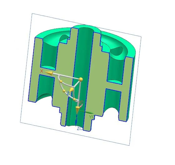
Machined aluminum-core samples
Validate a modifiable sample route before committing to the production mold.
After selecting aluminum, we refined the wheel section and machined core samples. The review covered the shaft bore, mounting faces, concentricity direction, load areas, rubber coverage, core positioning and interface preparation.
The cores were overmolded into trial wheels, then checked for dimensions, appearance, rubber-to-core interface, assembly and running feedback. Weather, temperature, wear and visible marking checks followed the customer's agreed method. Findings returned to the structure, compound or process until the customer confirmed the sample route.
Engineer-led project path
Eight controlled stages from customer requirements to mass production.
1. Customer requirement review
Confirm dimensions, load, speed, temperature, environment, floor, wear and marking criteria.
Release condition Inputs and acceptance responsibilities are recorded.
2. Engineering condition conversion and DFM
Convert the requirement record into structure, material, interface, process and inspection inputs before detailed development.
Release condition DFM inputs and the project verification route are agreed.
3. Compound design and validation
Develop and compare candidate formulas under agreed material and complete-wheel checks.
Release condition The compound route meets the project validation direction.
4. Core route review
Compare iron and aluminum for weight, strength, corrosion, machining, cost and bonding.
Release condition The customer and engineering team select the aluminum direction.
5. Machined sample cores
Machine aluminum cores, inspect critical features and prepare the overmolding interface.
Release condition Released sample cores are identified for wheel trials.
6. Trial wheels and customer testing
Overmold trial wheels, inspect them and complete agreed assembly and running checks.
Release condition Customer confirmation authorizes production tooling.
7. Production mold
Develop the mold around core location, flow, venting, parting, flash, cure and demolding controls.
Release condition First-article and pilot results remain consistent with the confirmed sample.
8. Mass production
Fix the approved compound, core drawing, surface preparation, mold and process window.
Release condition Qualified batches are released under the agreed inspection and acceptance criteria.
Batch quality controls
Keep the approved sample route connected to every production batch.
- Controlled compound version, core drawing, surface preparation and molding instructions.
- Incoming core checks, first-article approval, in-process inspection and final release.
- Appearance, dimensions, overmolding completeness and interface checks against agreed criteria.
- Batch identification, abnormal isolation, change control and inspection records.
- Customer confirmation before approved material, tooling or process changes.
Customer-confirmed result
After repeated requirement, compound, core, sample and tooling iterations, the customer confirmed the project result and the wheel entered mass production. This outcome applies to the documented project conditions; it is not a universal guarantee for every robot or floor.
Performance and disclosure boundary
Weather resistance, high and low temperature performance, wear resistance and no obvious black marking depend on the compound, structure, load, speed, floor, environment and test method. Final conclusions for a new project remain subject to agreed technical documents, sample records and customer acceptance.
RFQ and engineering follow-up
Send the wheel drawing, robot conditions and acceptance method for a focused review.
Include dimensions, load, speed, operating temperature, environmental exposure, floor material, running cycle, wear target, marking method, expected volume and target schedule.